
Key Takeaways
- G-code is the standard programming language for Computer Numerical Control (CNC) machines and 3D printers.
- MIT researchers developed the first numerical control language in the late 1950s.
- The Electronic Industries Alliance standardized G-code as RS-274-D in 1979.
- G-code commands use alphanumeric syntax to direct machine tools through precise Cartesian movements.
- CAD/CAM software generates G-code automatically from 3D models for most production workflows.
The Fundamentals of G-Code: Definition and History
G-code is the primary programming language for CNC machines and 3D printers, used in automated manufacturing worldwide. Machine controllers read G-code instructions sequentially and convert each command into precise motor movements.
What is G-Code? The Machine Programming Basics
G-code is a specialized programming language that controls CNC machines and other machine tools through geometric operations. Each instruction pairs an address letter with a numeric value. CNC machines read these commands line by line and execute motor movements with sub-millimeter repeatability.
The language encodes tool movement paths in a Cartesian coordinate system (X, Y, Z axes). The command G01 X50 Y25 F200 moves the machine tool to X=50, Y=25 at 200 mm/min. CNC machines execute that instruction, then advance to the next line.
The Evolution of G-Code
MIT researchers developed the first numerical control language in the late 1950s to automate milling machines. The RS-274 standard was first published in 1963 by the Electronic Industries Alliance, making G-code one of the oldest programming languages still in active use.
The Electronic Industries Alliance published the standardized RS-274-D in 1979. The international equivalent, ISO 6983, followed in 1982. The core G-code vocabulary has remained stable across six decades of CNC and automated manufacturing.
How G-Code Controls Machine Movement
G-code translates digital coordinates into axes movement. The CNC controller calculates intermediate positions and drives servo motors along the programmed path.
The Structure of G-Code Commands
Each G-code command block pairs address letters with numeric values:
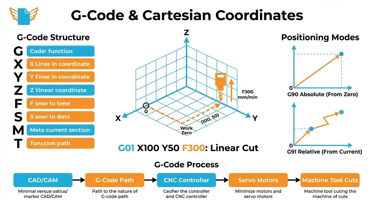
- G: preparatory command (motion type, operating mode)
- X, Y, Z: coordinate positions along the three linear axes
- F: feed rate in mm/min
- S: spindle speed in RPM
- M: miscellaneous machine function (spindle on/off, coolant)
- T: tool number for automatic tool changers
Multiple addresses combine on one line. G01 X100 Y50 F300 commands a linear cut to (100, 50) at 300 mm/min.
Coordinate Systems in G-Code Programming
All G-code movement uses a Cartesian coordinate system with three primary axes: X (left-right), Y (front-back), and Z (up-down). The machine establishes a work zero point and measures every tool position relative to that reference. The coordinate system defines the machine workspace and enables precise positioning.
G-code supports two positioning modes. Absolute mode (G90) moves the tool to an exact coordinate from the work origin. Relative mode (G91) moves the tool a specified distance from the current location. Most programs use G90 and switch to G91 only for incremental operations.
G-code Working Process (Machine and Operator Perspectives)
On the operator’s side, G-code production starts with a CAD model. CAD/CAM software generates G-code tool paths from programmer-defined machining strategies, bridging digital design and physical CNC production.
From the machine’s side, the CNC controller reads the program block by block. The controller calculates intermediate points and drives servo motors. Machine tools (mills, lathes, routers) cut the workpiece as each G-code instruction executes.
The Structure of G-code Commands
G-code is a structured programming language with consistent syntax rules. Understanding command structure allows machinists to read, write, and troubleshoot programs without relying entirely on CAM-generated output.
Anatomy of a G-code Line
Each program line is called a block. A typical block contains one or more address-number pairs:
N010 G01 X75.5 Y-20.0 Z5.0 F150 ; Linear moveN010 is the optional line number. G01 commands linear interpolation. X75.5 Y-20.0 Z5.0 defines the target coordinates. F150 sets feed rate to 150 mm/min. The semicolon opens a comment that the CNC controller ignores at runtime. Not every block needs all components; a valid G-code line can be as short as G28 Z0.
G-code Syntax
G-code command syntax and code format follow conventions defined in RS-274-D. Address letters are uppercase; numbers can be integers or decimals. Comments begin with a semicolon. Programs open with a percent sign (%) and end with M30. The program number (such as O0001) identifies the program in the controller’s memory.
Reading G-code Block by Block
CNC controllers process G-code modally. Modal commands stay active until another command in the same group replaces them. Once G01 is active, every subsequent line executes as a linear move until the program changes the motion type. A machinist does not repeat G01 on every cutting line; modal behavior reduces G-code programs to the minimum necessary instructions.
Common G-Code Commands and Their Functions
Fewer than 20 G-code commands cover the vast majority of CNC programming.
| Command | Function | Example |
|---|---|---|
| G00 | Rapid positioning | G00 X0 Y0 Z5 |
| G01 | Linear interpolation | G01 X50 F200 |
| G02 | Clockwise circular arc | G02 X30 Y30 I15 J0 |
| G03 | Counterclockwise arc | G03 X10 Y10 I-10 J0 |
| G20/G21 | Inches / millimeters | G21 |
| G28 | Return to machine home | G28 Z0 |
| G54-G59 | Work coordinate offsets | G54 |
| G90/G91 | Absolute / relative mode | G90 |
Essential Movement Commands (G00, G01, G02/G03)
The four movement commands define every geometric tool path in G-code programming.
G00 (Rapid Positioning) moves the machine tool at maximum traverse speed. Each axis moves independently at maximum rate. G00 does not produce a straight-line path to the target, so it is used only for positioning between cuts, never for material removal.
G01 (Linear Interpolation) moves the tool in a straight line at the programmed feed rate. G01 is the primary command for flat surfaces, drilling, and straight profiles.
G02 and G03 (Circular Interpolation) direct the machine tool along a circular arc (clockwise for G02, counterclockwise for G03). Both require center-point offsets (I, J, K) or a radius value.
Setup and Configuration Commands Every Machinist Should Know
Setup commands establish the CNC operating environment before cutting begins. Correct setup is a critical step in CNC programming.
- G20/G21: set the unit system (inches or millimeters)
- G90/G91: select absolute or relative positioning mode
- G54-G59: select work coordinate system offset; G54 is the default
- G28: return the machine tool to its home reference position
These commands appear at the start of every G-code program and define the coordinate system context for all motion blocks.
Categories of G-code Commands by Function
G-code commands fall into five groups. Positioning commands (G00-G03) define the motion type and path. Mode commands (G90, G91, G20, G21) set the operating environment. Compensation commands (G41, G42, G43) apply tool offsets. Cycle commands (G81, G83, G84) execute canned drilling and tapping sequences. M-codes control auxiliary machine functions that complement G-code geometric instructions.
Detailed G-code Programming Example
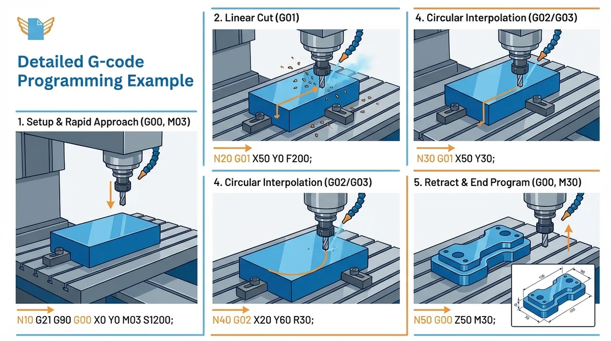
A complete G-code program shows how alphanumeric commands combine into a functional CNC machining operation. The example drills a single hole to a depth of 15 mm.
%
O0001 ; Program number
G21 G90 G17 ; mm, absolute, XY plane
M06 T01 ; Select Tool 1
S1200 M03 G54 ; Spindle 1200 RPM, work offset 1
G00 X25 Y25 ; Rapid to hole center
G81 Z-15 R5 F150 ; Drill cycle, depth -15mm
G80 G00 Z50 ; Cancel cycle, retract
M05 G28 Z0 M30 ; Stop, home, end
%
Step 1: G21 and G90 set millimeters and absolute positioning.
Step 2: M06 loads Tool 1; M03 starts the spindle at 1,200 RPM.
Step 3: G00 rapid-positions the machine tool to X25, Y25.
Step 4: G81 executes the canned drilling cycle to Z=-15 mm at 150 mm/min.
Step 5: M30 ends the program and resets the CNC controller for the next cycle.
G-Code vs M-Code: the Difference
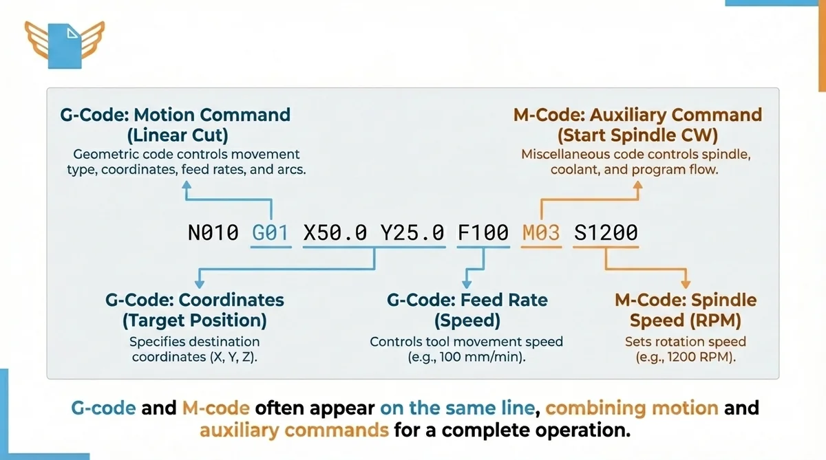
G-code and M-code appear together in every CNC program but serve distinct roles. Both originated at MIT and share the RS-274-D standard.
Geometric code (G-code) controls motion: movement type, coordinates, feed rates, and arcs. M-code (miscellaneous code) controls auxiliary commands: spindle, coolant, tool changes, and program flow control.
| Function | G-code | M-code |
|---|---|---|
| Straight-line cut | G01 | |
| Start spindle CW | M03 | |
| Turn on coolant | M08 | |
| Circular arc | G02/G03 | |
| Stop spindle | M05 | |
| End program | M30 |
M03 activates the spindle clockwise; M05 stops it. M08 turns on flood coolant; M09 turns it off. G-code and M-code appear on the same line. S1200 M03 sets spindle speed and starts rotation in one block.
Reading and Interpreting G-Code
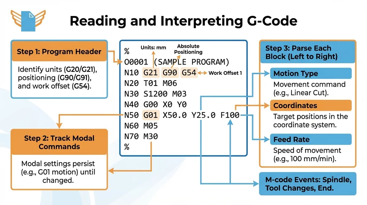
Reading G-code systematically reduces errors before material is cut. Every G-code file follows the same structural logic.
How to Read a G-Code Program Line by Line
Step 1: Read the program header. Identify units (G20/G21), positioning mode (G90/G91), and work offset (G54-G59). These define the coordinate system context for every line that follows.
Step 2: Track active modal G-code commands as you read. Modal settings persist until explicitly changed, so carry the current motion type and coordinate mode mentally through each block.
Step 3: Parse each block left to right: motion type, coordinates, feed rate. Confirm coordinates make physical sense relative to the current tool position. Note M-code events: spindle, tool changes, program end.
Decoding G-Code File Structure
A complete G-code file follows a predictable structure: initialization blocks first (units, positioning mode, offsets), then tool change blocks, then cutting operations, then retract commands and M30. CAD/CAM software generates this structure automatically from programmer-defined toolpath strategies. CNC controllers parse the file sequentially, so block order determines machine tool movement sequence.
G-Code Applications Across Manufacturing Technologies
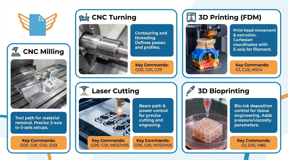
G-code controls machines across different manufacturing domains, from CNC machining to 3D printing and medical bioprinting.
| Technology | G-code Role | Key Commands |
|---|---|---|
| CNC Milling | Tool path for material removal | G00, G01, G02, G03 |
| CNC Turning | Contouring and threading | G00, G01, G33 |
| 3D Printing (FDM) | Print head movement and extrusion | G1, G28, M104 |
| Laser Cutting | Beam path and power control | G00, G01, M03/M05 |
| 3D Bioprinting | Bio-ink deposition control | G1, G92, M82 |
G-Code in CNC Machining: Milling, Turning, and More
Every CNC machine tool category relies on G-code for precise motion control. CNC milling machines use 3-axis to 5-axis setups. CNC lathes define contouring passes and threading. Grinding machines apply G-code for ultra-precise finishing. CNC routers cut wood, plastics, and composites for aerospace and furniture production.
Each machine type interprets the same core G-code commands. Lathe programs add G33 for thread cutting; milling programs rely on G02/G03 for profiled surfaces. The Cartesian coordinate system and modal behavior remain identical across all CNC machine tool categories.
How G-Code Powers 3D Printing and Additive Manufacturing
G-code serves as the control language for FDM 3D printers. Slicer software converts a 3D model into a G-code file that specifies print head movements, extrusion amounts, and temperatures. 3D printing utilizes the same Cartesian coordinate system as CNC machining; the E-axis controls filament extrusion.
3D bioprinting adapts standard G-code for bio-ink deposition in tissue engineering. Bioprinting G-code adds pneumatic pressure and viscosity parameters alongside standard movement commands.
Different Machines That Use G-code
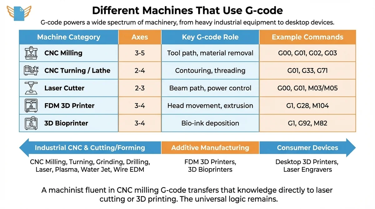
G-code powers a wide spectrum of manufacturing machinery, from heavy industrial equipment to desktop consumer devices. The table below shows how G-code implementation differs across major machine categories.
| Machine Category | Axes | Key G-code Role | Example Commands |
|---|---|---|---|
| CNC Milling | 3-5 | Tool path, material removal | G00, G01, G02, G03 |
| CNC Turning / Lathe | 2-4 | Contouring, threading | G01, G33, G71 |
| Laser Cutter | 2-3 | Beam path, power control | G00, G01, M03/M05 |
| FDM 3D Printer | 3-4 | Head movement, extrusion | G1, G28, M104 |
| 3D Bioprinter | 3-4 | Bio-ink deposition | G1, G92, M82 |
Industrial CNC machines: CNC milling machines (3-axis and 5-axis), turning centers and lathes, grinding and honing machines, drilling and boring machines.
Cutting and forming machines: Laser cutters for metals and plastics, plasma cutting tables for steel plate, water jet systems for heat-sensitive materials, and wire EDM machines for precision die work.
Additive manufacturing: FDM 3D printers (consumer and professional) and 3D bioprinters for medical applications.
A machinist fluent in CNC milling G-code transfers that knowledge directly to laser cutting or 3D printing. The address-letter, coordinate-value, modal-command logic is universal.
Getting Started with G-Code Programming
Learning G-code starts with the Cartesian coordinate system and letter-number syntax, building from simple positioning moves to complete machining sequences.
Essential Tools for G-Code Creation and Editing
CAD/CAM software generates G-code automatically from 3D models:
- Fusion 360 (Autodesk): industry-standard CAD/CAM with integrated G-code generation; free for non-commercial use with limitations
- UltiMaker Cura: FDM slicer that outputs print-ready G-code from STL files
- NC Viewer: free browser-based G-code viewer for program inspection and direct edits
- Notepad++: text editor machinists use for direct G-code file editing with syntax plugins
- DNA Studio 4 (CELLINK): bioprinting software with an integrated G-code editor for BIO X and BIO X6 bioprinters
Step-by-Step Process for Writing Effective G-Code
- Set the work zero point (X0, Y0, Z0) on the physical part.
- Write initialization blocks: units (G21), positioning mode (G90), work offset (G54).
- Add motion blocks: G00 for rapid positioning, G01/G02/G03 for cutting passes.
- Add M-code events: spindle on (M03), coolant on (M08), end program (M30).
- Simulate in NC Viewer before running on the CNC machine.
Popular G-code Editors and Software
NC Viewer provides free browser-based G-code simulation. Notepad++ supports syntax highlighting for direct G-code editing. UltiMaker Cura generates print-ready G-code from STL files. DNA Studio 4 (CELLINK) includes a G-code editor and toolpath visualizer for the BIO X6 bioprinter.
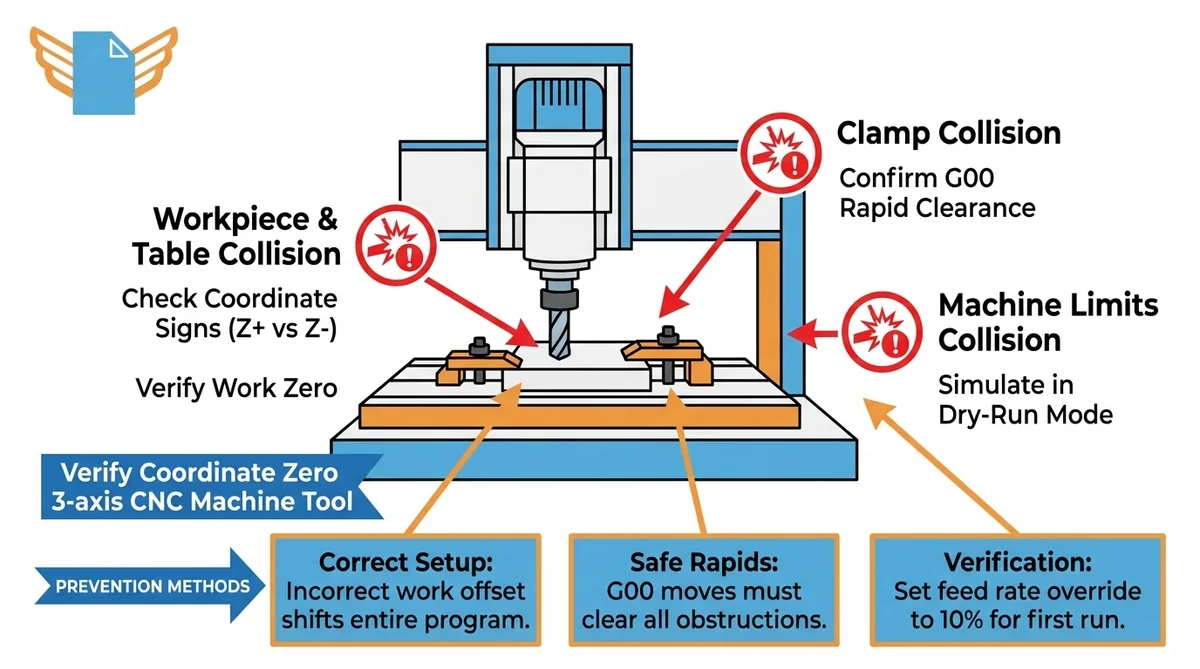
Safety Considerations in G-code Programming
G-code safety and CNC safety require machine collision prevention. A single G-code error can drive a tool into the workpiece at full rapid speed.
Critical checks before running any new G-code program:
- Verify the work zero point matches the physical CNC machine setup
- Check all coordinate values for sign errors; a negative Z where positive is expected drives the tool into the table
- Confirm G00 rapid moves clear all clamps and machine limits
- Set the feed rate override to 10% for the first run
- Simulate in dry-run mode before starting the spindle
Incorrect coordinate system setup is a leading cause of CNC machine collisions. Selecting the wrong work offset (G54-G59) shifts the entire G-code program, sending the machine tool into solid material at maximum rapid speed.
Troubleshooting Common G-Code Issues
| Problem | Likely Cause | Solution |
|---|---|---|
| Tool crash on G00 | Wrong work offset active | Verify G54-G59 before starting |
| Overshot position | Feed rate too high | Reduce F value; check acceleration |
| Arc error alarm | Invalid G02/G03 center point | Recalculate I/J values |
| Program stops mid-cycle | Syntax error or missing address | Check controller alarm; inspect block |
| Incorrect part dimensions | Cutter compensation not applied | Enable G41/G42; verify offset values |
G-code troubleshooting uses programming language debugging methodology: identify the error category, isolate the offending block, and determine whether the fault is in G-code syntax or machine setup values.
Preventive practices for G-code programming:
- Include G90 at program start to enforce absolute positioning
- Add Z retract moves before rapid traverses to guarantee clearance above fixtures
- Use M01 (optional stop) at key stages to inspect the part before continuing
- Comment every tool change and major operation for faster debugging
Machine tool responses (wrong depth, wrong position, alarm codes) point directly to specific G-code errors. Systematic debugging of G-code follows the same logic as any structured programming language.
Advanced G-Code Techniques for Optimization
G-code optimization and advanced techniques reduce cycle times and simplify program maintenance for professional CNC machinists.
Canned cycles replace repetitive sequences with a single G-code command. G81 drills a hole in one block instead of five. Peck drilling with automatic chip clearing is handled by G83. For tapping, G84 synchronizes spindle speed and feed rate precisely. This prevents thread damage on the machine tool.
Subroutines define a sequence once and call it repeatedly. M98 P0002 L5 calls sub-program O0002 five times, which suits drilling patterns or repeated profiling passes.
Parametric G-code programming uses variables and arithmetic. #1 = 25.0 assigns a value; G01 X#1 uses it as the X coordinate. A roughing cycle with 15 G01 moves (45 program lines) replaces with a single G71 turning cycle (6 lines) on a compatible CNC lathe controller, cutting program length by 87%.
The Future of G-Code and Machine Programming
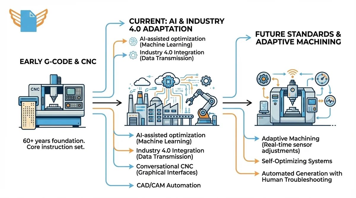
G-code has underpinned CNC manufacturing for over 60 years. CNC programming trends reflect machine programming evolution: the language adapts to AI and Industry 4.0 while its core instruction set stays unchanged.
Emerging trends in machine programming:
- AI-assisted optimization: machine learning tools suggest feed rate and toolpath changes to reduce cycle time
- Industry 4.0 integration: CNC controllers transmit production data to factory systems, with G-code as the machine-level execution layer
- Adaptive machining: sensors detect tool wear in real time and adjust G-code feed parameters mid-production
- Conversational CNC: graphical interfaces generate G-code from feature inputs, reducing manual coding
CAD/CAM software automates more G-code generation each year. Understanding G-code directly remains important for troubleshooting CAM programs.
Frequently Asked Questions
What does G-code mean?
G-code is the programming language that controls CNC machines and 3D printers. Standardized as RS-274-D in 1979, G-code delivers sequential instructions for tool movement, feed rate, and spindle speed using alphanumeric syntax readable by humans and machine controllers.
What is G-code used for?
G-code directs machine tools through precise operations: milling, turning, drilling, grinding, laser cutting, and 3D printing. CNC controllers convert each G-code instruction into motor movements. Parts with sub-millimeter accuracy are manufactured consistently across aerospace, automotive, and medical industries.
Is G-code a programming language?
Yes. G-code is a low-level programming language for numerical control machines. ISO and the Electronic Industries Alliance recognize it formally as ISO 6983 / RS-274-D. G-code communicates directly with machine hardware, not through a general-purpose software runtime.
What machines use G-code?
G-code controls CNC mills, lathes, grinding machines, routers, laser cutters, plasma cutters, water jet systems, and FDM 3D printers. Bioprinting systems use adapted G-code. Any machine tool requiring precise, repeatable Cartesian motion qualifies for G-code control.
What is the best G-code editor?
NC Viewer is the most accessible free browser-based tool for G-code visualization and edits. Notepad++ suits machinists who edit G-code directly. Cura and PrusaSlicer generate G-code from 3D models. Professional CAM tools such as Fusion 360 include full simulation modules.
Are there any safety considerations or precautions to keep in mind when programming G-code?
Yes. Incorrect coordinates, wrong work offsets, or missing retract moves cause crashes. Run new CNC programs at 10% feed rate override, use the controller’s dry-run mode before cutting, and verify the active work offset (G54-G59) before every run.
Are G-codes universal?
The core G-code vocabulary (G00, G01, G02, G03, standard M-codes) runs consistently on most CNC controllers. Manufacturers add proprietary extensions, so dialects differ between Fanuc, Haas, and Siemens. Programs may need modification between brands.
Is G-code hard to learn?
Fundamental G-code commands (rapid positioning, linear interpolation, circular arcs) are learnable in a few days for anyone comfortable with basic algebra and Cartesian coordinates. Simple CNC programs are achievable within one to two weeks. Parametric programming and multi-axis coordination require months of practice.
Do you have to be good at maths to understand G-code?
Basic G-code requires arithmetic and XYZ coordinate awareness. Circular arc calculations (I, J values) require geometry. For most production CNC programming, CAD/CAM software handles calculations automatically. The programmer focuses on machining strategy rather than manual computation.
Is G-code used on all CNC machines?
G-code is the dominant programming language globally, but some machines use conversational interfaces that generate G-code internally. A small number use proprietary languages. G-code remains the most widely implemented standard across industrial and consumer CNC equipment.
How does feed rate work in G-code commands?
Feed rate, set with the F address, defines how fast the machine tool moves during controlled motion. In metric mode (G21), F is millimeters per minute. G01 X100 F200 moves to X=100 at 200 mm/min. Feed rate is a modal G-code setting and persists until changed. G00 moves ignore F.